meta data for this page
This is an old revision of the document!
Software interface
There are several software interfaces available to monitor the status of the RECS®|Box system. These are the Management WebGUI and a REST API providing XML based monitoring and management functionality.
Management WebGUI
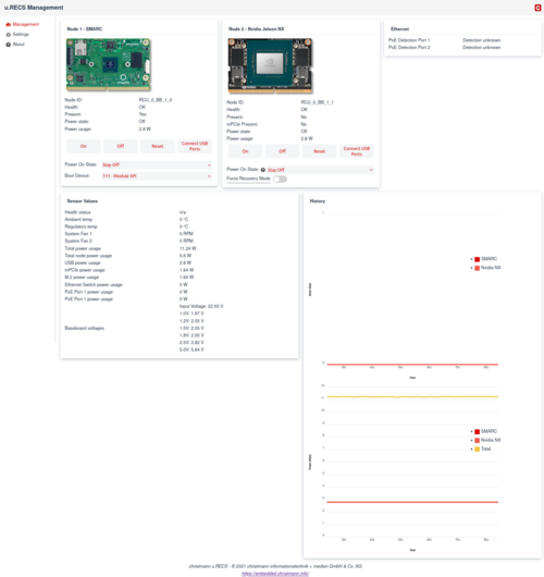
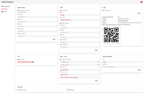
The Management WebGUI is established on every u.RECS unit. Accessible by any known browser on the assigned IP address and the default port 443. The following views are dependent on the device and assembly.
In general these symbols have the following meaning on every page:
 | Everything is OK. Also indicated by a green line in a graph. |
 | Warnung. Something is wrong, but the system is still fully functional. The system has to be checked so the problem doesn't get worse. Indicated by a yellow line in a graph. |
 | Critical Error. The system must be checked immediately and maybe has to be shut down to prevent hardware damage. indicated by a red line in a graph. |
Management
Settings
REST API
Access
The RECS®|Box Management API is accessible via the IP-Address or the hostname of the TOR-Master of the cluster. The basic URL of the API has the format https://TOR-Master/REST/ or http://TOR-Master/REST/.
Accessing the REST API requires HTTP Basic authentication. The authenticated user has to be in the “Admin” or “User” group to be able to execute the POST/PUT management calls.
Components
The RECS®|Box Management API makes all hardware components in the cluster available as XML trees in software. The following components are supported by the API:
| Attribute | Description |
|---|---|
node | A single node |
baseboard | Overview about the baseboard that can be equipped with 1 or 2 nodes |
system | Overview of the whole system (baseboard + node) |
lorawan | Enables communication to LoRaWAN application servers |
Many resources also return lists of components. These are named according to the scheme <component name>List (e.g. nodeList, rcuList) and contain the elements of the list.
Node
Example XML:
<nodeList>
  <node maxPowerUsage="26" baseboardPosition="0" architecture="unknown (SMARC)" baseboardId="RCU_0_BB_1" voltage="5.64"
    actualNodePowerUsage="2.8" actualPowerUsage="2.8" state="0" lastPowerState="0" defaultPowerState="0"
    rcuId="RCU_0" health="OK" lastSensorUpdate="1369" id="RCU_0_BB_1_0" present="true" bootDevice="0"/>
  <node maxPowerUsage="27" baseboardPosition="0" architecture="ARM + iGPU" baseboardId="RCU_0_BB_1" voltage="5.64"
    actualNodePowerUsage="2.8" actualPowerUsage="2.8" state="0" lastPowerState="0" defaultPowerState="0"
    rcuId="RCU_0" health="OK" lastSensorUpdate="1369" id="RCU_0_BB_1_1" present="false" mpciePresent="false" forceRecovery="false"/>
</nodeList>
The following table shows the possible attributes (some are optional) and their meaning:
| Attribute | Description | Unit | Data type |
|---|---|---|---|
id | Unique ID for referencing the component | - | String |
actualPowerUsage | Actual power consumption of a node (Node + PEG) | W | Double |
actualNodePowerUsage | Actual power consumption of a node (Node only) | W | Double |
actualPEGPowerUsage | Actual power consumption of a PEG card | W | Double |
maxPowerUsage | Maximum power the node can draw | W | Integer |
baseboardId | ID of the baseboard which hosts the node | - | String |
baseboardPosition | Position of the node on the baseboard | - | Integer |
state | Power state of the node (0=Off, 1=On, 2=Soft-off, 3=Standby, 4=Hibernate) | - | Integer |
architecture | Architecture (x86, arm, UNKNOWN) | - | String |
health | Health status of the node (OK, Warning, Critical) | - | String |
inletTemperature | Temperature of the inlet air | °C | Double |
outletTemperature | Temperature of the outlet air | °C | Double |
highestTemperature | Highest temperature measured on the node's baseboard | °C | Double |
voltage | Supply voltage of the baseboard | V | Double |
lastSensorUpdate | Timestamp of the last sensor update | ms | Long |
macAddressCompute | MAC address of the NIC connected to the compute network (optional) | - | String |
macAddressMgmt | MAC address of the NIC connected to the management network (optional) | - | String |
In accordance to the component node the API offers nodeList which returns multiple instances of node.
Baseboard
Example XML:
<baseboard serialNumber="90380CA9D524" rcuPosition="0" baseboardType="u.RECS" id="RCU_0_BB_1" lastSensorUpdate="358"
    rcuId="RCU_0" inputVoltage="22.93" boardVoltage1V0="1.97" boardVoltage1V2="2.05" boardVoltage1V5="2.05"
    boardVoltage1V8="2.05" boardVoltage2V5="2.82" boardVoltage5V0="5.64" totalPowerUsage="11.24" usbPowerUsage="2.8"
    mPciePowerUsage="1.64" m2PowerUsage="1.64" ethSwitchPowerUsage="0" poePowerUsagePort1="0" poePowerUsagePort2="0"
    regulatorsTemperature="0" ambientTemperature="0" fanSpeed="100" systemFan1Rpm="0" systemFan2Rpm="0" loraJoined="false"
    loraJoinEui="0000000000000000" loraDevEui="1234561234561234" loraAppKey="01234567890123456789012345678901"
    loraVendorID="FFFF" loraVendorProfileID="0001" poeDetectionStatusPort1="0" poeDetectionStatusPort2="0"
    firmwareVersion="0837db2">
  <nodeId>RCU_0_BB_1_0</nodeId>
  <nodeId>RCU_0_BB_1_1</nodeId>
</baseboard>
The attributes have the following meaning:
| Attribute | Description | Unit | Data type |
|---|---|---|---|
id | Unique ID for referencing the component | - | String |
rcuId | Unique ID of the RECS®|Box Computing Unit hosting the baseboard | - | String |
rcuPosition | Position of the baseboard inside the RECS®|Box Computing Unit | - | Integer |
infrastructurePower | Power usage of the infrastructure components on the baseboard | W | Double |
lastSensorUpdate | Timestamp of the last sensor update | ms | Long |
baseboardType | Type of the baseboard (CXP, APLS) | - | String |
nodeId | List of IDs of the nodes installed on the baseboard | - | String |
temperatures | List of temperatures measured on the backplane | °C | Double |
In accordance to the component baseboard the API offers baseboardList which returns multiple instances of baseboard.
System
Example XML:
<system>
  <baseboard serialNumber="90380CA9D524" rcuPosition="0" baseboardType="u.RECS" id="RCU_0_BB_1" lastSensorUpdate="1403"
      rcuId="RCU_0" inputVoltage="22.93" boardVoltage1V0="1.97" boardVoltage1V2="2.05" boardVoltage1V5="2.05"
      boardVoltage1V8="2.05" boardVoltage2V5="2.82" boardVoltage5V0="5.64" totalPowerUsage="11.24" usbPowerUsage="2.8"
      mPciePowerUsage="1.64" m2PowerUsage="1.64" ethSwitchPowerUsage="0" poePowerUsagePort1="0" poePowerUsagePort2="0"
      regulatorsTemperature="0" ambientTemperature="0" fanSpeed="100" systemFan1Rpm="0" systemFan2Rpm="0" loraJoined="false"
      loraJoinEui="0000000000000000" loraDevEui="1234561234561234" loraAppKey="01234567890123456789012345678901"
      loraVendorID="FFFF" loraVendorProfileID="0001" poeDetectionStatusPort1="0" poeDetectionStatusPort2="0"
      firmwareVersion="0837db2-dirty">
    <nodeId>RCU_0_BB_1_0</nodeId>
    <nodeId>RCU_0_BB_1_1</nodeId>
  </baseboard>
  <nodeList>
    <node maxPowerUsage="26" baseboardPosition="0" architecture="unknown (SMARC)" baseboardId="RCU_0_BB_1" voltage="5.64"
      actualNodePowerUsage="2.8" actualPowerUsage="2.8" state="0" lastPowerState="0" defaultPowerState="0" rcuId="RCU_0"
      health="OK" lastSensorUpdate="1403" id="RCU_0_BB_1_0" present="true" bootDevice="0"/>
    <node maxPowerUsage="27" baseboardPosition="0" architecture="ARM + iGPU" baseboardId="RCU_0_BB_1" voltage="5.64"
      actualNodePowerUsage="2.8" actualPowerUsage="2.8" state="0" lastPowerState="0" defaultPowerState="0" rcuId="RCU_0"
      health="OK" lastSensorUpdate="1403" id="RCU_0_BB_1_1" present="false" mpciePresent="false" forceRecovery="false"/>
  </nodeList>
</system>
Resources
The resources are split into monitoring resources (for pure information gathering) and management resources (for changing the system configuration or state).
Monitoring
For monitoring the following resources are available:
| Attribute | Description | HTTP Method |
|---|---|---|
/node | Returns a nodeList with all nodes of the system | GET |
/baseboard | Returns an overview of the baseboard including the installed nodes | GET |
/system | Returns an overview of the baseboard and all nodes | GET |
Management
The management of individual components can be found under the “manage” path of the component.
| Attribute | Description | HTTP method | Parameter |
|---|---|---|---|
/node/{node_id}/manage/power_on | Turns on the node with the given ID and returns updated node XML | POST | |
/node/{node_id}/manage/power_off | Turns off the node with the given ID and returns updated node XML | POST | |
/node/{node_id}/manage/reset | Resets the node with the given ID and returns updated node XML | POST | |
/node/{node_id}/manage/select_kvm | Switches the KVM port of the RECS®|Box Computing Unit containing the node to the node with the given ID and returns updated node XML | PUT | |
/rcu/{rcu_id}/manage/set_fans | Sets the overall fan speed of the RCU with the given ID and returns the curent status of the RCU | PUT | percent={value} |
LoRaWAN
The LoRaWAN interface allows up and downlink connections to an application server. Packets can be scheduled and collected by interfacing the Management REST API
| Attribute | Description | HTTP method |
|---|---|---|
/lorawan/queue | Responds with incoming LoRaWAN packets linked to the API key in the request body XML | POST |
/lorawan/queue | Schedules uplink packet to the application server defined in the management interface XML | GET |
/lorawan/manage | Manages LoRa PHY settings XML | GET |
Example XML queue GET / POST:
<lorawan apikey="...">
<packetbody>lora packet content in base64</packetbody>
</lorawan>
Example XML manage:
<lorawan masterkey="...">
<band>eu</band>
<txpwr>14</txpwr>
<txsf>7</txsf>
<rx2wsf>9</rx2wsf>
</lorawan>
In order to remotely manage the RECS power status via LoRaWAN, the Application Server must send the downlink command payload in following format:
<l masterkey="">
  <power>1</power>
<l>
The master and API keys are managed in the RECS web interface.
Errors
Information about the success or failure of management requests are returned via HTTP status codes. Please have a look at RFC2616 for an overview about the defined HTTP status codes.


