

meta data for this page
Physical interface
RCU interface
Front panel connectors
The following items are located at the front of a RECS®|Box RCU:
- Two line display
- A five button D-pad
- Four internally switched LAN ports that connect to the 1GbE management network of the nodes
- One LAN port that connects to the internal management controller (marked with “Management”)
- Four USB ports that can be switched to every module via KVM
- One HDMI port that can be switched to every module via KVM
- Six (Antares) or 18 (Arneb) LAN ports that connect to the compute network of the labelled node (network speed depends on the installed netboards Netboard installation


Control panel
The display on the front panel of the RCU shows the status of the unit on multiple screens that automatically change every couple of seconds and are updated live.
| Antares | Arneb | Description |
|---|---|---|
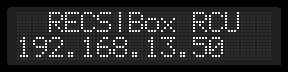 | Shows the IP address of the RCU. | |
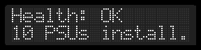
 |  | Displays the current health status of the RCU and the number of compute modules installed. On the Antares the number of PSUs installed is also shown. |
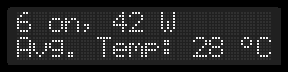 | In the first row the number of currently turned on compute modules is shown along with their current power consumption. The second row shows the current average temperature. | |
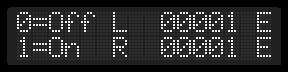
 |  | Shows the node on/off status for each baseboard. For ARM baseboards the number of nodes on is shown (0-4). A dash (“-”) indicates baseboards that are not populated or where not found. In case of an Antares RCU also the status of the power supplies is shown. “L” and “R” mark the orientation of the display and are shown as looking onto the front panel. |
The buttons next to the display will be used for a local management menu later on. Currently they are not used except for the “down” button: Press this key for a few seconds to safely shut down the management controller in the RCU before disconnecting power to the unit.
Power connectors
Antares
The Antares has one male C14 jack on the back that can be connected to an 230V power outlet using a standard C13 cable. Both built in power supplies are connected to this jack.
The exhaust air openings in the back must be kept free. Keep that in mind when installing cables behind the Antares.
Arneb
The Arneb has six 12V power connectors on the back. These are connected to an Alasco power supply. The upper male plug is the (+) pin and the bottom female plug is the (-) pin. All six connectors are joined together to two copper rails. One (+) and one (-). The plugs are coded and can only be plugged in in the right way.
How many of these connections to the Alasco are needed depends on the hardware configuration and the total power consumption of the Arneb.
RPU interface
Front panel connectors
The Alasco power supply unit has the following items in its frontpanel:
- Two line display
- One LAN port that connects to the internal Colibri with the management software of the power supply
LCD display
| Display | Description |
|---|---|
 | Shows the IP address of the RPU |
 | Displays the current health status of the RPU and the number of power supplies installed. |
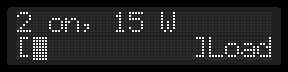 | Shows the numer of power supplies that are currenty on, and the power provided by the RPU. A percentage bar (10% steps) of the load is shown in the lower line. |
 | Shows the on/off status for each power supply (0=off 1= on). A dash (“-”) indicates power supplies that are not populated or where not found. “L” and “R” mark the orientation of the display and are shown as looking onto the front panel. |
Power connectors
The Alasco has one male C19 jack on the back that can be connected to an 230V power outlet using a C20 cable. Connect this cable to an 16A fuse, as the Alasco can require up to 3600W.
There are nine 12V plugs in the back, that can be connected to one or more Arnebs via the coded connectors. The upper male plug is the (-) pin and the bottom female plug is the (+) pin.
Sensors
Each Baseboard of the RECS®|Box system includes five temperature sensors that are regularly polled by the management software. This data is available in raw format via all software interfaces provided by the TOR Master. Additionally, the TOR Master calculates some derived temperatures: Inlet- and outlet temperature (Arneb only) as well as the highest temperatures on baseboard, RCU and cluster level.
Locations
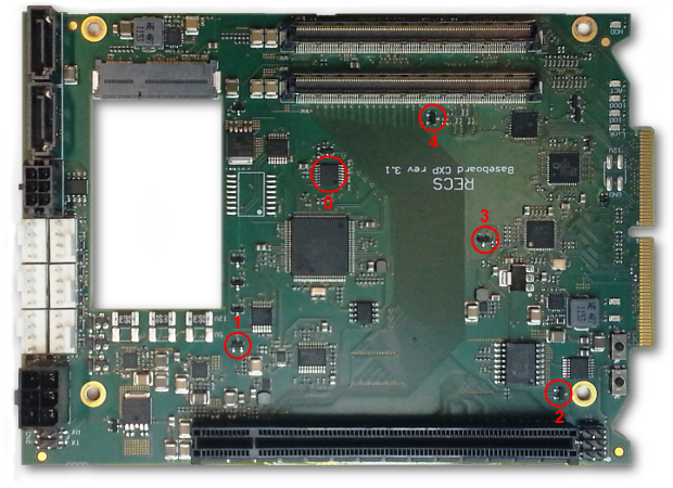
The following pictures indicate the location of the various temperature sensors on the baseboards along with their indices in the management data. The golden finger contacts on the right side of the picture always point towards the backplane.
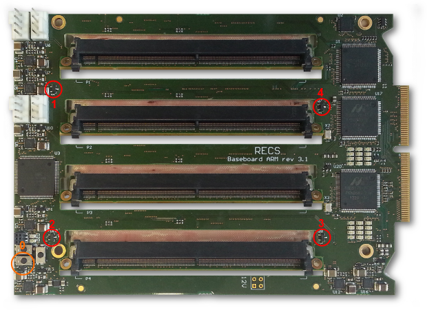 Fig. 3: Temperature sensors on ARM baseboard. Orange: Bottom side
Please note that temperature sensor 1 on the ARM baseboard (near the four fan connectors) is somehow thermally connected to the voltage regulators (located between the four fan connectors). This results in high temperature of this sensor if the modules 1 and 2 are powered on and consuming a lot of electrical power.
Assignment
Depending on baseboard type and location, the Arneb RCU calculates inlet- and outlet temperature for each baseboards by averaging different temperature sensor readings. The following table shows which sensor(s) are used, where “left” and “right” are seen as looking onto the LCD of the unit.
| Temperature | Type | Left | Right |
|---|---|---|---|
| Inlet | CXP | 1 | 3 |
| APLS | 1, 2 | 3, 4 | |
| Outlet | CXP | 3 | 1 |
| APLS | 3, 4 | 1, 2 |