

meta data for this page
Server installation
The following chapter will give you an overview on how to install an maintain your RECS®|Box.
When working on the RECS®|Box always wear ESD protection equipment.
Rack mounting
The Antares version of the RECS®|Box comes with premountet rack-rails. These can be used to install the Antares into any 19“ rack.
The following chapter is copied from the original user manual of the rails:
- Slide chassis member (smallest) is removable. Separate slide members by lifting left hand side lever up, and right hand side lever down. Keep slide chassis members with original outer members.
- Slide has front and rear adjustable EIA brackets. Attach front brackets to outer slide member using #8-32 machine screws by aligning access slots on brackets to outer member holes. Front brackets can be mounted flush or 1/2” [12.7 mm] back from front of slide based on user needs.
- Establish distance from front cabinet rail to rear cabinet rail and attach rear brackets to slide. Do not fully tighten rear bracket mounting screws until final adjustment is made.
- Insert removable locator pin into center hole of brackets.
- Slide will mount to various cabinet rails at various locations on side of chassis. See illustrations at right.
- Place slide into desired position and fully extend against EIA rails. Locator pins will support slide and bar nut while attaching screws.
- Attach slide to EIA rail with #10-32 screws and fasten with bar nuts. Once screws are secure, remove locator pins. Do not fully tighten screws until final adjustment is made.
- Mount slide chassis members (smallest) to the chassis.
- With cabinet members in the open or closed position, bring ball retainer to full forward position. Install chassis by engaging the slide members and close completely. Locks will engage on initial insertion and must be released to fully close. Check slide alignment by opening and closing the chassis. Any sign of binding indicates lateral stress or misalignment.
- Adjust slide position until movement is smooth. Tighten all screws and complete installation.
NOTE: To remove chassis, lift the lever on the left hand slide up and the lever on the right hand slide down.
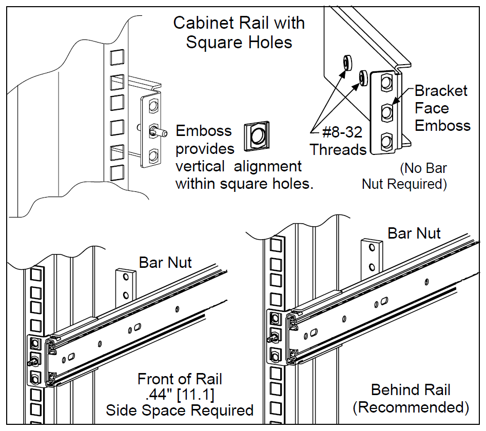 Fig. 1: Mounting overview
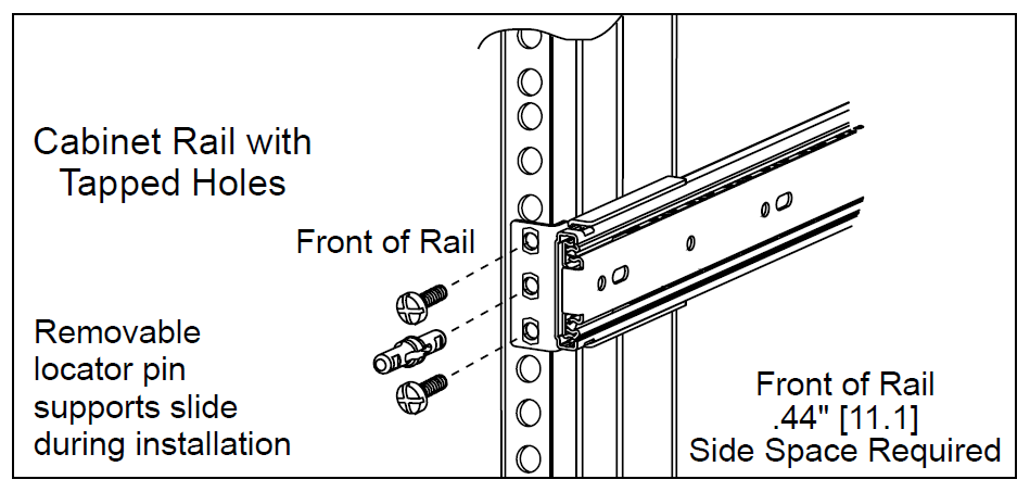 Fig. 2: Detailed view of infront of the rail mount
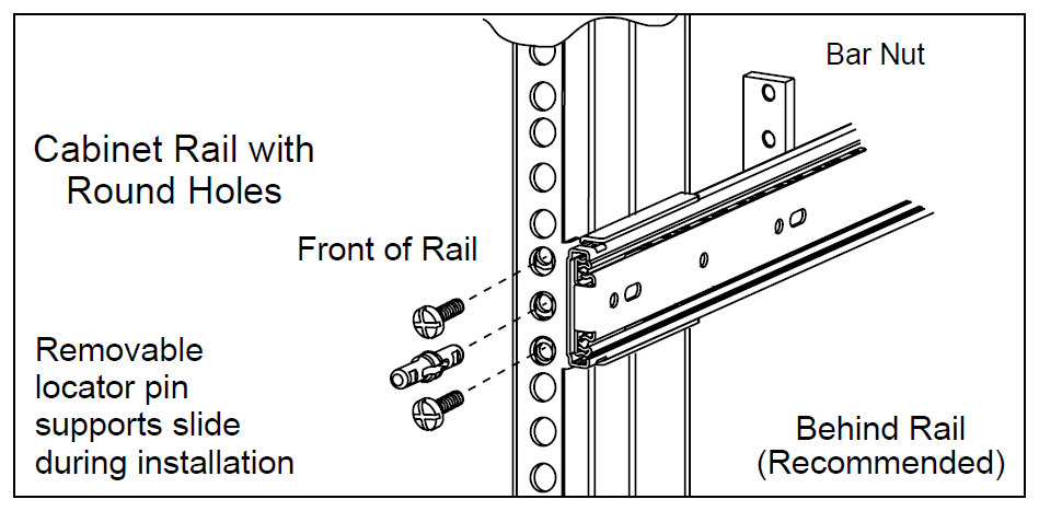 Fig. 3: Detailed view of behind the rail mount
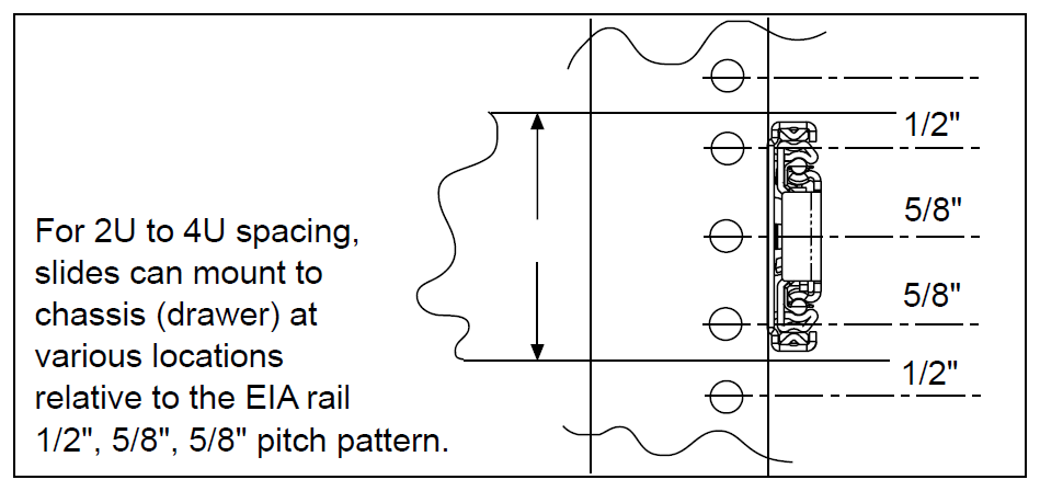 Fig. 4: Slide frontview
Opening/closing the case
To open the case first make sure, that no heavy load is on the modules. Because this can lead to overheating when the top cover is removed.
Always make sure that no tools or any other stuff can fall into the case.
Antares
When opening the case watch out not to touch the 230V cables or connector block in the back that lead to the power supplies. This can result in a danagerous electric shock.
Opening the case
First unscrew the M3 knurled screw (A) at the top back of the Antares. It may be necessary to pull the Antares out of the rack further than the rails allow. To to this pull the Antares out until the rails lock in place, and then use the levers to the left and right (as described in Rack mounting) to slide the Antares over the locking point. But don't pull to far, as the Antares could slip out of the rails!
Then slide the cover back (B) and carefully lift the cover so that the hooks don't get stuck and bend.
Closing the case
Place the cover onto the Antares so that the hooks fit into the holes in the chassis.
Then slide the cover to the front (B) while pushing the hooks downwards into the holes if they are stuck.
At last tighten the M3 knurled screw (A) at the top back of the Antares.

Arneb
Opening the case
Unscrew the 14 (six on top, eight on the sides; marked red below) M3 screws using a T8 Torx screwdriver and lift the cover.
Closing the case
Place the cover on top of the Arneb and check if the screwholes of the cover align with the ones in the chassis.
If this is not the case the cover is placed in the wrong direction. Tighten all 14 screws (marked red below) using a T8 Torx screwdriver.
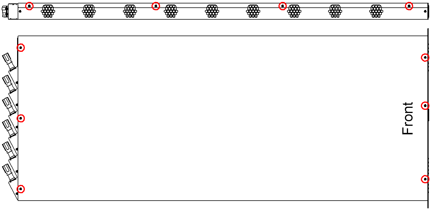 Fig. 6: Cover screws (red circle); the four screws on the right side are not shown
Alasco
Do not open the case of the Alasco.
If you encounter a problem with the Alasco please contact your vendor.
Baseboard replacement
When removing a Baseboard always work very carefully and do not bend the baseboards nor use greater force to get them into place.
Pay attention to the newtork cables that are located right under the baseboards. They or the baseboards can be damaged if not handeled with care. Check if they are still properly fixed to the case and don't stack over each other more than 2 mm.
It is recommended to turn the systempower off when changing a baseboard.
COM Express Baseboard
Remove the two M2,5 screws (B) with a T8 Torx screwdriver from the mSATA drive, and the four M3 screws (A) with a 5,5mm hexagonal nut.
Then lift the baseboard a bit at the end where the fan connectores are. And while moving it a bit to the left and right gently pull the baseboard out of the connector on the backplane.
Before plugging in a new baseboard make sure that there is a robust and isolating tape (like Kapton tape) taped onto the PCIe pins, that come out of the bottom of the board.
To plug the baseboard in procede the opposite way as removing it.

ARM Baseboard
The baseboard can be replaced when the Apalis modules are plugged in. And it is not recommended to remove the plasic module-holders. If an Apalis-holder is broken try to fix it with superglue without removing it from the baseboard.
Remove the four M3 screws (marked red) with a T10 Torx screwdriver. It can be handy to use a T9 Torx screwdriver for the screw in the top right on the picture below, when the Apalis modules are still in place.
Then lift the baseboard a bit at the end where the fan connectores are. And while moving it a bit to the left and right gently pull the baseboard out of the connector on the backplane.
To plug the baseboard in proceed the opposite way as removing it.

Compute module installation
When changing a module shut this module down and turn the power for the module off in the managemant GUI.
The rest of the system can stay powered.
COM Express module
Before installing a Com Express module check if the RAM is installed, and that the heatspreader is correctly mounted, and depending on the module if all thermal pads are in place. Also the orientation of the heatsink fins has to follow the airflow trough the case. If it is an Antares the cooling fins have to point from the front to the back. In an Arneb case they have to point from side to side.
The screwholes where the module lays on the spacer bolts (8 mm in height) have to be free. Or smaller spacer bolts (5 mm high) have to be installed.
- When the module is ready to be plugged in place the two holes next to the COM Express connector over the corresponding spacer bolt. Then slide the outer CXP connector into the outer connector on the baseboard. Do this while tilting the module a bit, so that only the outer connector slides in
- Then push the module down where the connector is by pressing on the heatsink. While holding the pressure push the module down with a luffing movement on the end where no CXP connector is. The module should now slide into the second CXP connector and be in place
- check if the module is mounted correctly and is not loose

When starting the module for the first time after installation, it is necessary to set the time again, as the modules don't have an own battery and are provided with electricity for the clock by the battery on the frontpanel.
Apalis module
Before installing an Apalis module check if the thermal pads are installed, and that the heatsink doesn't touch any electronic components. Especially where the breakouts in the heatsink are. Also check if the screws are tightend and the clamp is locked in place.
When bending the plasic holder be carefull and do not bend them too far as they could break off. If this happens try to repair them using superglue without detaching the plasic holder from the baseboard, as this can lead to a broken baseboard.
- insert the module into the Apalis connector on the baseboard
- push the module down while bending the plastic holder a bit to the outside so that the heatspreader can slide past the holder
- release the pastic holder back to the original position and let the module snap up into the plastic holder
- check if the module is locked in place

To remove a module proceed with the opposite procedure.
Netboard installation
All netboards (1GbE or 10GbE) have the same connector (as seen below) underneath and are all mounted on the three connectors on the backplane. Each netboard provides the compute network to the two baseboards that are plugged in right next to them. It is also possible to mix different netboards, as they are independent of each other.
- To install a netboard simply place it over the connector with the correct orientation.
- Align the connectors with the help of the smaller one.
- Carefully and mostly parallel push the netboard down into the connector while wobbleing the board a bit.


Extension card installation
It is possible to install an extension card like a graphics card on the PCIe x16 slot of an v3.1 CXP baseboard.
A special riser card is needed to connect the card. The I/O shield of the card has to be removed. The 6-pin power connector on the baseboard can deliver up to 300W, but a special cable may be required to connect the 6-pin plug to the card, as the cards have different connectors (6pin, 8pin or a mix).
Please contact your vendor about this cable.
 and 6-pin power connector (red) on an v3.1 CXP BB")

When installing an extension card make sure that it will be cooled propperly.
Antares
One full sized dual slot card can be built into the back of the Antares. The card will then be connected to node 6. In the Antares, there are no mountingpoints in the chassis, so these have to be glued on to fix the card in position. Due to the fact that the airflow in the Antares is beeing changed, wenn installing a extension card, the fans have to be rearranged and additional air baffles have to be installed. The exact location of the fans and the air baggles depends on the size of the card and combination of CPU modules built into the Antares.

Arneb
The Arneb can hold single slot cards. If the card is too long no node or netboard can be placed where the card is. There are grid plates available, that can be used to build a holding structure for the card onto.
It is possible to install a dual slot card, if the heatsing is small enough not to touch the backplane.
An example of an extension card that requires the space of the netboard installed in an Arneb can be seen below.

Fan replacement
A fan that has damaged blades schould be replaced immediately, because the bearing will break very fast due to the imbalance and resulting vibrations.
When changing a fan on a working system be very carefull not to touch the blades or get any cables into the running fans. Also watch out that the system is not overheating during the changing process.
Watch out that the plugs are correctly placed on the baseboard. As a short circuit or misalignment of the pins will damage the baseboard.
Open the case according to the Opening/closing the case chapter of this wiki. First disconnect the fan from its power source and make sure the cable is not stuck anywhere.


Antares
- To remove the fan simply drag it out of the mounting plate diagonally.
- Unscrew the anti-vibration-rubber from the broken fan with a PH2 screwdriver, and screw them diagonally onto the new fan so that the cable and airflow point in the right direction when installed.
- Push the fan back into the mounting plate.
- Arrange the cable under the fans and connect it.


Arneb
- Unscrew the two screws that hold the fan to the chassis with a PH2 screwdriver.
- Replace the fan with a new one considering the airflow direction.
- Tighten the two screws.
- Plug the cable onto the baseboard.